The fuel level sensor (FLS). Assembly, scheme, trade
Greetings esteemed readers! For several years I wrote on the topic of our monitoring service vehicles, equipment, which produced reveal inner aspects of production and work in General. In this article I want to talk about the full cycle of production of this very important element of the systems GPS monitoring and control, as the fuel level sensor (the search engines know him as the DUT). Is the theory that all drawings and diagrams for Assembly of this product. Anyone interested — read on.
0. Membership
Looking ahead to say, there will be three articles in this I will talk about the simplest case of determining the level of diesel fuel (diesel only, used on petrol technology is absolutely prohibited, as explosive). The following articles, unless of course the reader will wonder, consider digital fuel level sensor, and in the end I plan on posting a schematic and the firmware of the device to be monitored, which is described in this article.
1. A bit of theory
The most popular sensors measure the level of fuel is an electric condenser comprising two tubes placed in each other, established tank with fuel, the level of which is measured. Diesel freely into the space between the tubes, changes in the fuel level in the tank is the change in capacitance of the sensor.
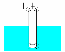 When you change the fuel level in the tank changes the relative permittivity of the space between the capacitor plates as the dielectric constant of the fuel and air in General case are different. And since the capacity is directly proportional to the dielectric constant of the insulator, the result is changed and the capacitance sensor. Sensors are mostly manufactured from aluminum or copper because they are less exposed to the corrosive environment. Of the many ways of measuring capacitance values of the capacitor and the subsequent transformation of its capacity in a proportional change in DC voltage at the output was chosen PWM method, as a fairly simple and reliable, but at the same time providing the necessary level of measurement accuracy. Immediately requires a reservation is the easiest in terms of Finance and simple enough to assemble FLS method for determining the level of diesel fuel.
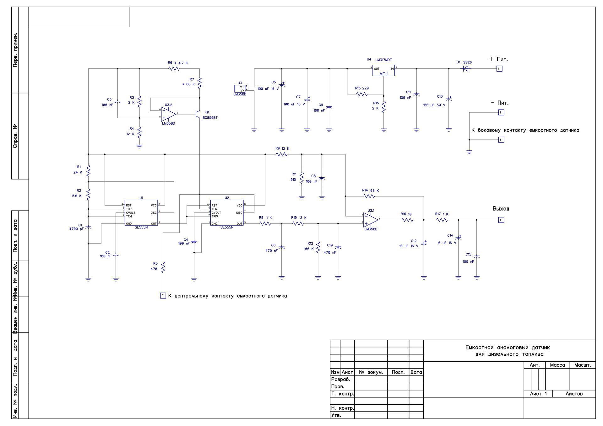
 2. Job description electrical circuit of fuel level sensor
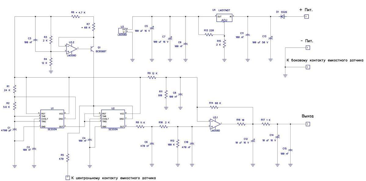
Figure 2. Schematic diagram of fuel level sensor (FLS) (the big scheme here)
To increase the stability and accuracy of the testimony of all of the circuit elements are used with a minimum temperature coefficient. The used resistors with 1% tolerance, the chip is selected with superior performance in contrast to the household counterparts, for example: SE555N is NE555N and the LM358D is LM258D.
On chip U1 SE555N and elements R1, R2 and C1 are assembled by a master oscillator. As it strongly depends on the stability of the readings as the capacitor C1 is used precision polystyrene capacitor K71-7 1%, usually they were established in the Soviet color TVs in the master generators of the horizontal scan. Can be replaced with something modern, but the availability and price of these capacitors makes them very attractive, and they were born in the distant year, when the Soviet Union very well monitored the quality of the items.
Output from the 3rd chip U1 rectangular pulses trigger a one-shot, assembled on the chip U2 SE555N. As the one-shot capacitor, using a sensor placed in the fuel, so its capacity will depend on the fuel level, and therefore, the width of the pulse at the output 3 of the chip U2 will also be changed to fuel level.
Output 3 of the chip U2 pulses are applied to the integrator, assembled on the elements R8 and C6.
Further integrated voltage formed at the capacitor C6 is supplied to the low pass filter performed on the R10 and C10.
Then, the DC voltage supplied to a DC amplifier, performed on the chip U3.1.
From the output of 1st IC U3.2 the signal through the filter, made on the elements R17, C12, C14 and C15 is supplied to the output.
Resistor R16 is used to prevent self-excitation of the amplifier when the capacitive load.
Divider made on the resistors R9 and R11 provides the required DC offset for the operation of the DC amplifier in the linear mode.
Voltage regulator for powering the electronic circuit placed on the classical scheme on the chip U4 LM317MDT.
In the end, at the output, we get the analog signal an empty tank 1.8 V full 6.0 (there is a dependence on height FLS), which is linear and directly proportional to the fuel level in the tank\tank\storage. Then, applying the Kalman filter, you can remove the jump fuel, the calculation of the average consumption, etc.
In reality it will look like this:
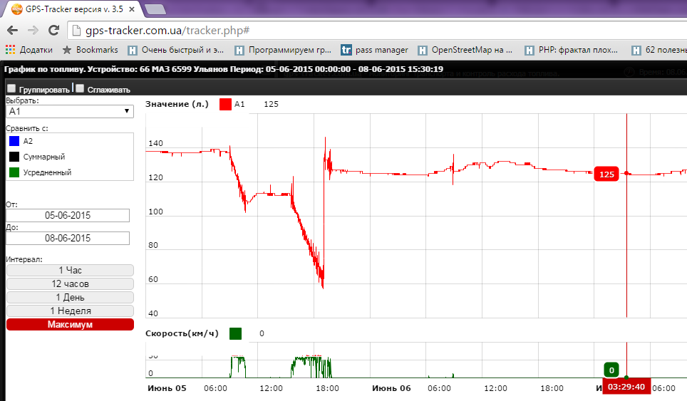
Graph of fuel level + speed.
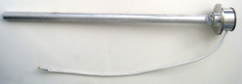
3. The drawing of a fuel level sensor,
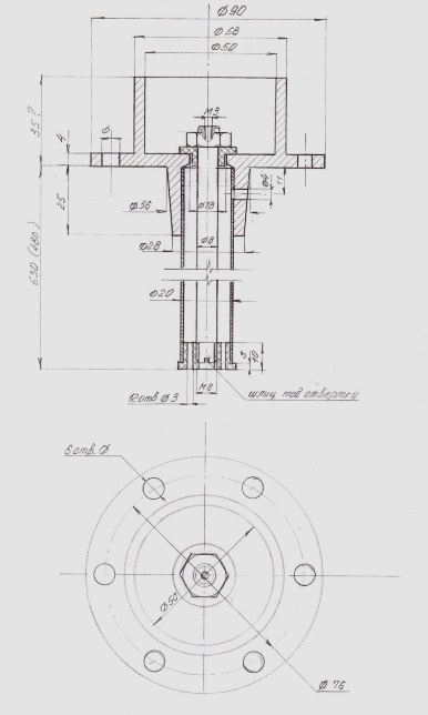
FIGURE 3. The drawing of a fuel level sensor (link to great drawing)
Mentioned that is used mainly aluminum, as can be seen from the drawing, the outer tube is soldered in any suitable way to the head DUT. In the manufacture of its sensors, we use the welding, since I have access to it, though not the most aesthetically beautiful, but reliable and time-tested. Inside there is an aluminum rod for fixing which is threaded in the upper part. Bushings are used from a special fluoropolymer which is the most tolerant of diesel fuel.
4. Summary
This solution is built, the vast majority of fuel level sensors GPS presented on the CIS market and the world. Each manufacturer makes its own changes to increase the measurement accuracy of the fuel level, such as an accelerometer, temperature sensors, digital signal processing, and more. I presented scheme is very simple, ready for work, as they say, in the fields without any difficulties. Dear reader with straight arms could make any modifications that you can use for his purposes and for commercial purposes.
PS. A bit erotic about how this nod is installed on the equipment see here.


Комментарии
Отправить комментарий